High-voltage product overview
VCB Panels
Vacuum circuit-breaker panel solutions configured against the approved high-voltage system design. Vostok Technologies engineers each VCB panel to the project-specific single-line diagram, protection philosophy, operating sequence and customer-approved component makes.
Purpose and operating principle
Project-specific HT switching and protection
VCB panels are developed as project-specific assemblies. The operating principle, component selection and internal arrangement are coordinated around the approved electrical design, protection coordination study and required operating sequence. No standard catalogue ratings are assumed; all parameters are confirmed against the approved project specification.
Typical duties include incoming switching and protection, bus-section control, outgoing feeder protection, transformer incomer protection and tie-breaker arrangements, subject to the approved scope.
Applications
Typical applications
- High-voltage incoming switching and protection
- Bus-section and bus-coupler control
- Outgoing feeder protection for HT motors and transformers
- Transformer incomer and differential protection
- Captive power plant and co-generation switchgear
- Industrial, pharmaceutical, infrastructure and utility projects
Engineering approach
Features and engineering scope
- Vacuum circuit-breaker (VCB) switching for high-voltage duties
- Draw-out or fixed-mounted VCB arrangement as per approved scope
- Numerical protection relays — overcurrent, earth fault, differential (as required)
- Busbar arrangement and metering per approved single-line diagram
- Interlocking scheme designed against the approved operating philosophy
- Control fascia with indicating lamps, selector switches and annunciation
- Secondary wiring and terminal identification per approved drawings
- Enclosure construction and IP rating per approved installation conditions
Project-specific parameters
Technical specification
All electrical parameters are defined against the approved project specification. Values shown below indicate the basis of selection — not standard catalogue ratings.
- System voltage
- As per approved project specification
- Rated current (busbar / feeder)
- As per approved project specification
- Short-circuit withstand (Ics / Icw)
- As per approved project specification
- VCB make and type
- Customer-approved make; draw-out or fixed
- Protection relay
- Numerical type; functions per approved scope
- Busbar material
- Copper or aluminium per approved specification
- Enclosure and IP rating
- Per approved installation conditions
- Applicable standard
- Confirmed against approved project scope
Protection and control
Protection and control options
- Overcurrent and earth-fault protection (50/51, 50N/51N)
- Differential protection (87) where specified
- Under-voltage and over-voltage protection (27/59) where specified
- Directional overcurrent (67) where specified
- Busbar protection scheme where specified
- Auto-reclose (79) where specified
- Metering: current, voltage, power, energy (as per scope)
- SCADA / remote monitoring interface (as per scope)
Safety
Safety interlocks
- Mechanical interlocking between VCB and earthing switch
- Draw-out position interlocks (service, test, isolated)
- Door interlocking with VCB in closed position
- Key interlocking scheme per approved operating philosophy
- Padlock provisions on isolating and earthing devices
- Anti-pumping relay on closing circuit
Available configurations
Available configurations are developed from the approved single-line diagram, system voltage, fault level, protection philosophy, operating sequence and customer-approved component makes. Arrangement, internal separation, cable entry, access, interlocks, monitoring and future expansion provisions are finalised during engineering review.
Construction and installation
Enclosure construction, sheet thickness, mounting arrangement, surface treatment, paint shade, indoor or outdoor suitability and degree of protection are selected only against the approved installation and environmental requirements. Cable entry, earthing provisions and access arrangements are confirmed during engineering review.
Quality assurance
Testing and documentation
- Approved drawing review prior to manufacture
- Incoming material and component inspection
- Enclosure fabrication and dimensional check
- Busbar and wiring inspection
- Mechanical operation and interlock functional check
- Electrical continuity and insulation-resistance test
- Secondary injection test on protection relays (where specified)
- Functional test of control, indication and annunciation circuits
- Final inspection and FAT documentation (where specified in scope)
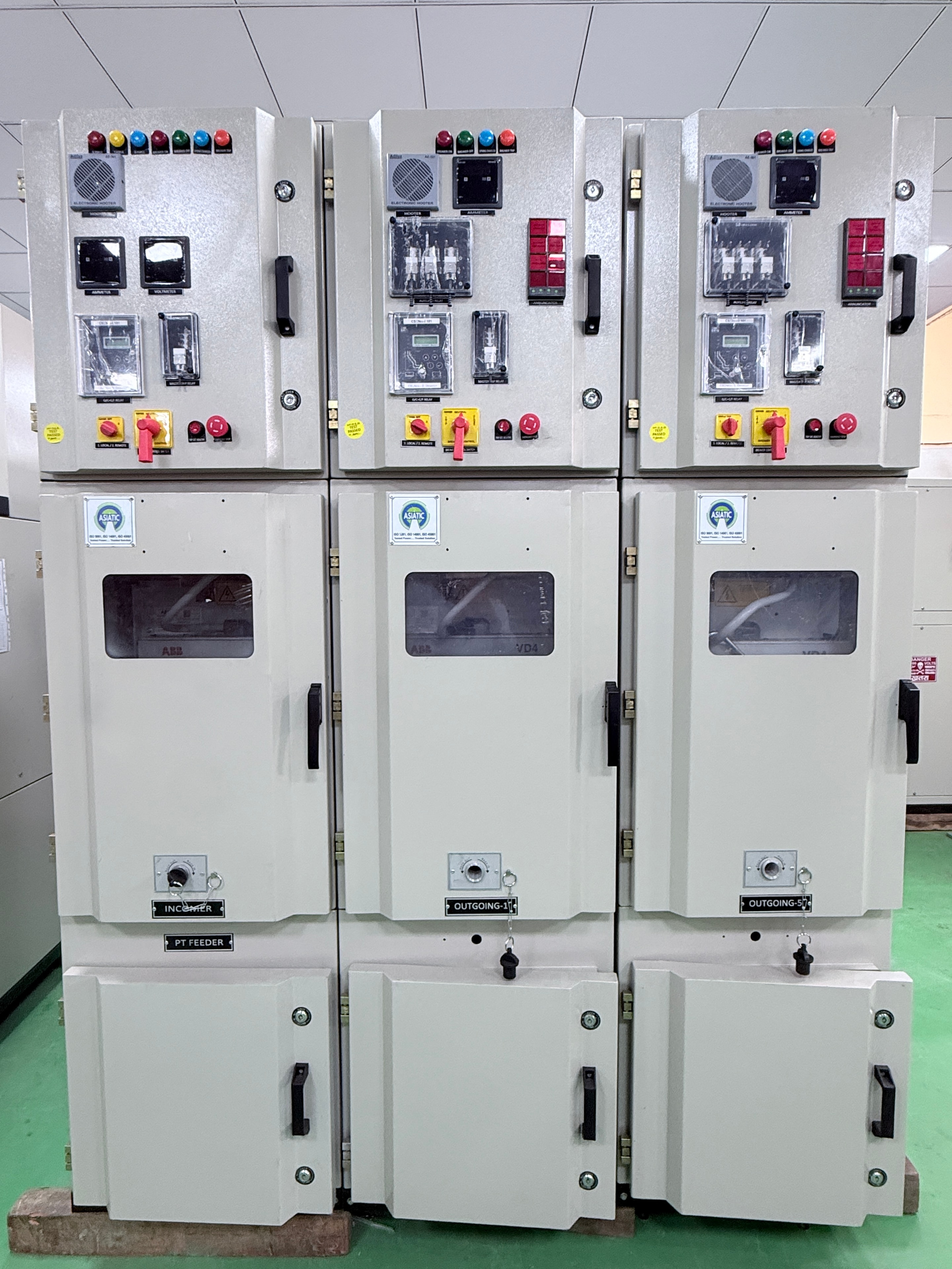
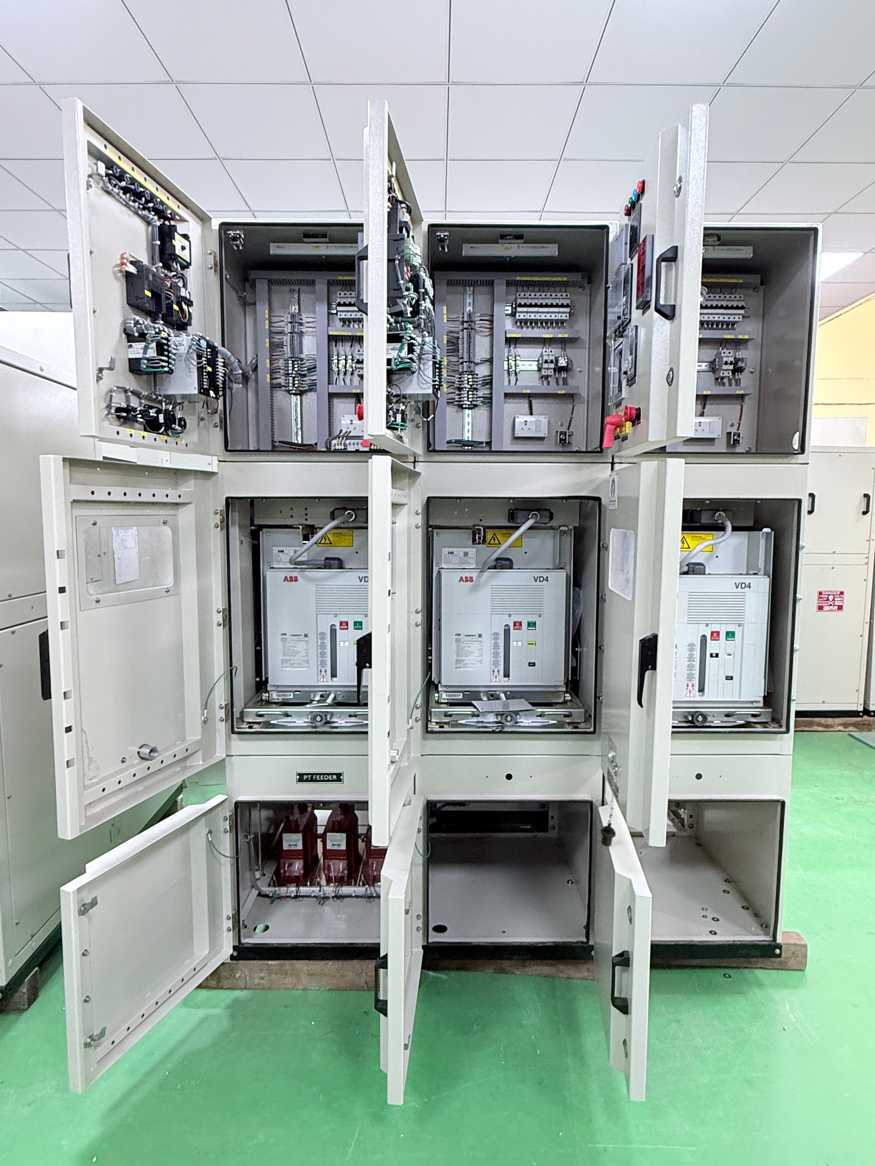
Product photography
VCB Panel — actual product
Frequently asked questions
What information is needed to begin VCB panel engineering?
Provide the approved single-line diagram, system voltage, fault level, protection philosophy, operating sequence, preferred component makes and required documentation scope. The engineering team will prepare a project-specific technical proposal.
Are voltage ratings and fault levels shown as standard values?
No. All electrical parameters — system voltage, rated current, short-circuit withstand, protection settings — are defined against the approved project specification. They are not presented as standard catalogue values on this page.
Can draw-out and fixed-mounted VCB arrangements both be supplied?
Both arrangements are considered against the approved project scope. The selection is confirmed during engineering review based on the operating philosophy, maintenance requirements and site conditions.
What protection relay makes are used?
Protection relay selection is aligned with the customer-approved make list. Relay functions are configured against the approved protection philosophy and coordination study.
Can FAT documentation and test reports be provided?
FAT documentation, test records and inspection reports are included where they form part of the approved project scope. Availability and format are confirmed during the project review.
Get in touch
Request a quote or technical consultation
Share your approved single-line diagram, system voltage, fault level and protection requirements. The Vostok Technologies engineering team will prepare a project-specific technical proposal.
What to include in your enquiry
- Approved single-line diagram
- System voltage and fault level
- Protection philosophy and coordination study
- Operating sequence and interlocking requirements
- Preferred component makes
- Installation conditions and enclosure requirements
- Required documentation and FAT scope